
Raypak Gas-Fired Heaters
Models 206A, 266A, 336A and 406A. These heaters hand out their own 24 VAC on a seven-pin connector and expect you to switch it. Send voltage the other way and the control board is destroyed — Raypak says so in as many words.
The seven-pin remote connector
The heater supplies power out through a seven-pin connector to either a toggle switch or the switch contacts of a third-party remote. Your contact simply makes or breaks the circuit the heater has already energised. Raypak requires the supplied seven-pin connector be used for both two-wire and three-wire arrangements.
| Conductor | Function |
|---|---|
| BLU | 24 VAC out from the heater |
| BLK/ORN | Return for a Pool call |
| ORN/BLK | Return for a Spa call |
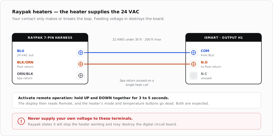
Two-wire, on-off control
Use this where only one heating function is wanted. Because the module becomes the thing that decides when heat is needed, what you set on the heater depends on whether the module or the heater is measuring water temperature.
| If the controller... | Set the heater to |
|---|---|
| Has its own temperature sensor | POOL or SPA mode with the temperature at the highest setting available, so the heater never becomes the limit |
| Has no sensor of its own | POOL or SPA mode at the setpoint actually wanted, for example 102 F for a spa |
Turning remote operation on
- 1
Restore power with the wiring complete
The seven-pin connector should be made up and plugged in before this step.
- 2
Hold UP and DOWN together for 3 to 5 seconds
That toggles remote operation. The second line of the display alternates even when the unit is showing No Demand.
- 3
Confirm the display reads Remote
The heater indicates that a remote system is in control by showing Remote on the display. That is the handover confirmed.
- 4
Prove the contact
Call for heat from the app and confirm the heater begins its ignition sequence, then release the call and confirm it shuts down.
Cable
- Remote wiring must be run in its own conduit, and must not run parallel to high voltage lines.
- Under 30 ft: stranded, minimum 22 AWG, 600 V, twisted with a 1.5 to 2.5 in lay, jacketed.
- Over 30 ft: minimum 20 AWG, 600 V, same lay, shielded and jacketed.
- Maximum cable length 200 ft (61 m).
When it does not fire
| Symptom | Where to look first |
|---|---|
| Contact closes, nothing happens | Remote operation not activated. Hold UP and DOWN for 3 to 5 seconds. |
| Display never shows Remote | Same cause — the heater is still in local control. |
| Board dead after wiring | Voltage was fed into the remote terminals. This is the failure Raypak warns about. |
| Heater will not exceed a temperature | Its own setpoint is acting as the limit. Raise it if the module owns regulation. |
| Nothing works and the model is millivolt | Millivolt heaters have no remote capability. |
Sources
- Raypak, Gas-Fired Pool and Spa Heater Installation and Operation Manual, models 206A-406A and 207A-407A — remote control installation, the seven-pin connector, harness colours, remote activation and cable requirements
- iSmart Module relay driver board — KiCad schematic and BOM. H1/H2 and AUX1/AUX2 are optocoupled dry relay contacts (N.C / COM / N.O)