
Pentair MasterTemp Heater
MasterTemp accepts either a fireman's switch across two terminals or RS-485 on its COM port. Both are straightforward. What is not forgiving is the 24 VAC circuit behind the fireman's switch, which destroys the control board if line voltage reaches it.
Choosing between the two methods
| Fireman's switch | RS-485 | |
|---|---|---|
| Wiring | Two conductors, dry contact | Two data conductors plus a common |
| Module output | H1 or H2 dry contact | PORT A or PORT B |
| What you get | On or off only | Setpoints, status and alarms |
| Front panel | Stays usable | Buttons inactive, shows RS-485 Control |
The fireman's switch is the simpler retrofit and works on any MasterTemp. RS-485 is the better result where the heater supports it, because faults surface in the app instead of on a panel nobody looks at.
Fireman's switch
The heater ships with a jumper fitted across the fireman's switch terminals, which is what allows it to run standalone. Remove that jumper and put your contact in its place. Closing the contact completes the heater's own 24 VAC control circuit and allows it to fire.
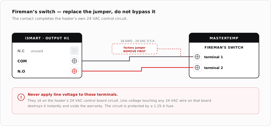
- The contact must be rated for 24 VAC at 0.5 A, because it carries the heater's own control circuit rather than a signal.
- Use 18 AWG wire with at least 3/64 in (1.2 mm) insulation rated to 105 C.
- Never apply line voltage to these terminals.
- The fireman's switch circuit is protected by a 1.25 A fuse on the heater. A blown one points at a wiring fault, not a failed heater.
- Route the wires through the knock-outs provided in the bottom of the control box.
RS-485
The heater's COM port is J4 on the control panel board, reached by routing the cable in through the exhaust panel. Pentair's own procedure calls for a drilled hole with a strain relief or flexible conduit and an insulating bushing, cable ties securing the run to the existing harness, and the wires kept off the exhaust.
| Pin | Colour | Signal | iSmart Module |
|---|---|---|---|
| 1 | Black | Common | PORT terminal G |
| 2 | Green | DATA- | PORT terminal B |
| 3 | Yellow | DATA+ | PORT terminal A |
Each heater on a bus needs its own address, set from the heater's front LCD menus. The default is 1 and the range is 1 to 16. A single heater can be left at the default.
When it does not fire
| Symptom | Where to look first |
|---|---|
| Nothing on a heat call | Factory jumper still fitted, or the contact wired across N.C instead of N.O. |
| Heater runs constantly | Jumper left in place alongside the new contact. |
| Dead after wiring | The 1.25 A fireman's switch fuse, and then whether line voltage reached the control board. |
| Fires but cuts out early | Flow or the heater's own limits. The contact only requests heat. |
| RS-485 wired but silent | Green and yellow swapped, or the heater address clashing with another device. |
Sources
- Pentair, MasterTemp Pool and Spa Heater Installation and User's Guide — remote control connections, fireman's switch rating and fusing, RS-485 COM port J4 pin colours, heater addressing and the pump run-on requirement
- iSmart Module relay driver board — KiCad schematic and BOM. H1/H2 and AUX1/AUX2 are optocoupled dry relay contacts (N.C / COM / N.O); PORT A-D are an unbuffered RS-485 pass-through