
Jandy VSFloPro Pumps
VSFloPro talks to a controller over a four-wire RS-485 interface. The wiring is quick. The step people miss is that the pump's own local controller has to come off first — it and an automation system cannot both drive the pump.
Remove the local controller first
Many VSFloPro units ship with a local controller display fitted on the motor — the JEP-R variable-speed controller, or an iQPUMP01 interface. That controller is what drives the pump on a standalone installation, and it occupies the same RS-485 interface an automation system needs. It has to come off.
This is not just a physical obstruction. The pump's dip switches select which kind of controller it expects, so removing the display and setting the switches are two halves of the same job — do one without the other and the pump still will not answer.
- 1
Remove power from the pump
Disconnect the high voltage lines, or turn off the breaker feeding the pump. Jandy is explicit that failing to isolate is a shock hazard that can cause severe injury or death.
- 2
Open the controller cover
Lift the cover on its hinges to reach the variable-speed controller.
- 3
Free the controller
Remove the six screws holding the variable-speed controller to the controller base on the pump motor.
- 4
Detach the internal RS-485 cable
Disconnect the cable joining the controller's user interface to the controller base. Do not over-extend it as you lift the controller away from the motor.
- 5
Disconnect the motor cable assembly
Unscrew the four connector terminals and disconnect the wires. Do not cut this cable — see the warning below.
- 6
Stow the loose wire
Bundle it into the pocket in the controller base. It is what you would reconnect if the local controller ever went back on.
- 7
Close the pocket
Secure the pocket cover and gasket to the controller base with its six screws. The gasket matters — this is an outdoor enclosure.
- 8
Open the motor access cover
Remove the single screw and access cover so the new RS-485 run can be brought in to the motor PCB, then refit it once wired.
Set the dip switches
The dip switch block sits at the rear of the pump and does two jobs at once: it tells the pump what kind of controller is driving it, and it sets the pump's address. Switches 1 and 2 select the controller type — and the setting that means “an automation system” is the one you want.
| Switch 1 | Switch 2 | Switch 5 | Selects |
|---|---|---|---|
| OFF | OFF | ON | Automation controller — use this |
| ON | ON | ON | Local variable-speed controller |
| Switch 1 | Switch 2 | Selects |
|---|---|---|
| OFF | OFF | Automation controller — use this |
| ON | ON | Local variable-speed controller |
Switches 3 and 4 then set the pump address, and the table is the same on both families. Jandy documents three positions:
| Switch 3 | Switch 4 | Address |
|---|---|---|
| OFF | OFF | Default (first pump) |
| ON | OFF | Pump 2 |
| OFF | ON | Pump 3 |
| ON | ON | Pump 4 |
The connection
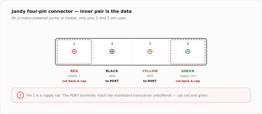
Jandy describes this as a four-wire RS-485 interface, shared with the AquaLink RS, PDA and Z4 controllers. Only two of those four conductors are data. The other two are a supply that a Jandy power centre provides for devices that need it — a mains-powered pump does not.
| Pin | Colour | Purpose | iSmart Module |
|---|---|---|---|
| 1 | Red | Supply positive | Not connected |
| 2 | Black | Data | PORT terminal A |
| 3 | Yellow | Data | PORT terminal B |
| 4 | Green | Supply common | Not connected |
Cable
- 22-24 AWG shielded, with the two data conductors as one twisted pair.
- Ground the shield at the iSmart Module end only.
- Keep the run out of conduit shared with the pump's power wiring.
- Daisy-chain rather than spurring off the middle of a run.
When it does not come up
| Symptom | Where to look first |
|---|---|
| Pump runs its own schedule, ignores the module | Local controller still fitted. On this pump that is the first thing to check. |
| No communication at all | Swap black and yellow. |
| Mainboard port dead after wiring | Pin 1 was landed on a data terminal. |
| Two Jandy devices, one erratic | Both on the same PORT. Split them. |
Sources
- Jandy Pro Series VS FloPro Variable-Speed Pump Installation & Operation Manual — four-wire RS-485 interface and connector positions 1-red, 2-black, 3-yellow, 4-green
- iSmart Module relay driver board — KiCad schematic and BOM. PORT A-D are an unbuffered RS-485 pass-through carrying A, B and G; supplies are 24 V, 5 V and 3.3 V with no 12 V rail; the MCP23017's port B is unconnected, so there are no switch inputs