
Jandy SpaLink RS 8-Function Spa Side Remote
The eight-button remote carries its own circuit board and speaks RS-485, which makes it the spa-side remote that fits this system: it lands on a PORT exactly like a pump or a heater rather than needing switch inputs.
The connection
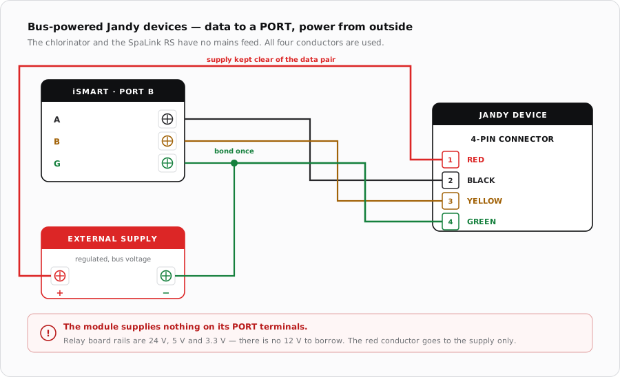
SpaLink RS joins the same four-pin bus as the rest of the Jandy range. On a Jandy power centre it is piggybacked onto the existing four-pin terminal bar alongside whatever else is already there. On the iSmart Module it takes a PORT of its own.
| Pin | Colour | Purpose |
|---|---|---|
| 1 | Red | Supply positive |
| 2 | Black | Data |
| 3 | Yellow | Data |
| 4 | Green | Supply common |
Installing it
- Mount above water level, in the spa tile line or the decking.
- Run conduit from the remote location back to the equipment pad before construction is finished — this cannot be retrofitted without breaking concrete.
- Use sweep elbows for turns so the cable can be pulled and, later, replaced.
- Keep the run out of conduit shared with any mains wiring.
When it does not respond
| Symptom | Where to look first |
|---|---|
| Completely dead | No supply on the outer pair. The remote has no other source of power. |
| Powered but no communication | Swap black and yellow. |
| Works intermittently in wet weather | Water ingress at the remote or in the conduit, not the bus. |
| Buttons do the wrong things | Firmware mapping rather than wiring — check the app's assignment. |
Sources
- Jandy SpaLink RS Remote Installation Manual — conduit requirements and the four-pin terminal bar the remote piggybacks onto
- Jandy Pro Series VS FloPro Installation & Operation Manual — four-wire RS-485 interface and connector positions 1-red, 2-black, 3-yellow, 4-green
- iSmart Module relay driver board — KiCad schematic and BOM. The MCP23017's port A drives the eight relays; port B (GPB0-GPB7) is unconnected and reaches no connector, so the board provides outputs only. Supplies are 24 V, 5 V and 3.3 V with no 12 V rail