
Jandy ePump / VS Plus Pumps
The ePump and VS Plus come with a Jandy communication cable already terminated in the four-pin connector. Two of its four conductors are all you need: pins 2 and 3, black and yellow.
Use the supplied cable
Jandy ships these pumps with a communication cable. Use it rather than making one up: the pump end is a moulded four-pin connector and the colours are what identify the conductors at the far end. Strip back and cap the two you do not use.
| Pin | Colour | Purpose | iSmart Module |
|---|---|---|---|
| 1 | Red | Supply positive | Not connected |
| 2 | Black | Data | PORT terminal A |
| 3 | Yellow | Data | PORT terminal B |
| 4 | Green | Supply common | Not connected |
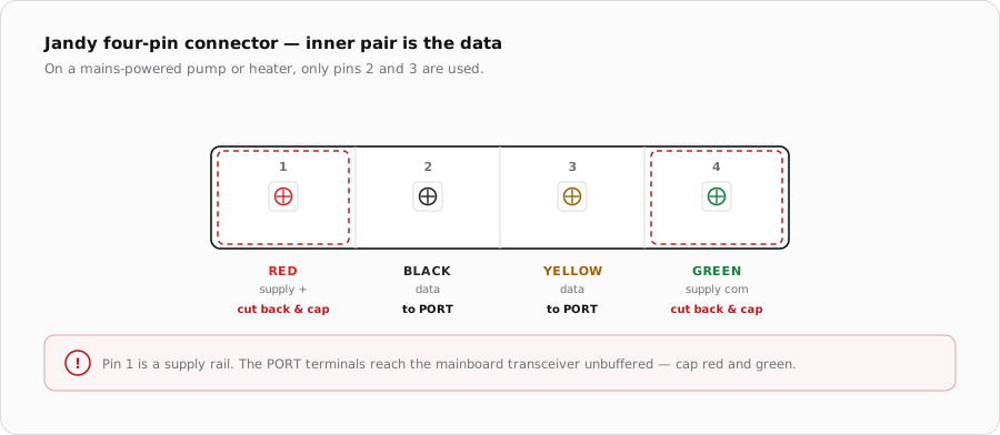
Pins 2 and 3 — black and yellow — are the two-way communication link. Pins 1 and 4, red and green, are the supply pair a Jandy power centre puts on the bus. The pump runs from its own mains supply and does not need them.
Cable
- Use the supplied Jandy cable where the run allows it.
- If it must be extended, use 22-24 AWG shielded and keep black and yellow as one twisted pair.
- Ground the shield at the iSmart Module end only.
- Keep it clear of the pump's power wiring.
When it does not come up
| Symptom | Where to look first |
|---|---|
| No communication | Swap black and yellow — Jandy does not label them A and B. |
| Mainboard port dead | Red or green landed on a data terminal instead of capped. |
| Intermittent | Data pair split across two twisted pairs, or shield grounded at both ends. |
| Works alone, fails with a second device | Both Jandy devices on one PORT. |
Sources
- Jandy Pro Series VS FloPro Variable-Speed Pump Installation & Operation Manual — four-wire RS-485 interface and connector positions 1-red, 2-black, 3-yellow, 4-green
- iSmart Module relay driver board — KiCad schematic and BOM. PORT A-D are an unbuffered RS-485 pass-through carrying A, B and G; supplies are 24 V, 5 V and 3.3 V with no 12 V rail; the MCP23017's port B is unconnected, so there are no switch inputs