
Hayward AquaRite (Legacy) Salt Water Chlorine Generator
Pre-S3 AquaRite units cannot join a bus on their own. They need Hayward's communication board fitted inside, and that board has to be fed 12 V before it will communicate — which the iSmart Module does not supply. Plan the extra supply before you quote the job.
Confirm you are on a legacy unit
If the main board already has an RS-485 connector on it, you have an S3 and should follow the AquaRite S3 guide instead — it wires directly and needs none of this. Legacy AquaRite units have no bus connection of their own. They reach an automation system only through Hayward's AQR Communication Board, a daughter board fitted inside the enclosure.
This is the whole difference between the legacy unit and the S3. On an S3, Hayward puts 12 V on position 1 and you simply leave it alone. Here, nothing energises that pin unless you provide it.
What you need beyond the usual
- Hayward AQR Communication Board, with its metal support bracket and the short 6 in wiring harness it ships with.
- A regulated 12 VDC supply. Size it for the communication board only — it is a signal board, not a load.
- Somewhere dry and rated to put that supply. It is additional equipment on the pad and needs its own protected position.
Fitting the communication board
- 1
Open the AquaRite
With power off and the cell cable disconnected, loosen the two retention screws and remove the dead front.
- 2
Make an entry for the cable
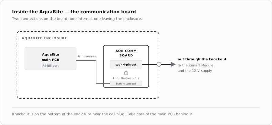
Remove a knockout on the bottom of the enclosure, near where the cell plugs in. Take care not to damage the main PCB behind it.
- 3
Mount the board
Locate the metal support bracket and press the communication board's four mounting feet firmly into the small holes in it.
- 4
Link the board to the AquaRite
Fit the short 6 in harness: one end to the bottom terminal of the communication board, the other to the AquaRite's RS485 port. This is the internal link and has nothing to do with the run back to the module.
- 5
Fit the outgoing terminal block
Install the four-pin terminal block in the top position on the communication board. That is the connection that leaves the enclosure.
- 6
Run out through the knockout
Take the field cable out through the knockout and dress it clear of the cell cable and any mains wiring.
Wiring it up
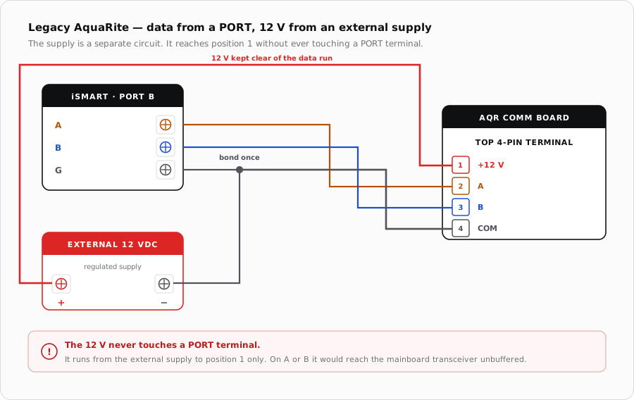
Four conductors leave the communication board, but they do not all go to the same place. Two carry data to a PORT, one carries the 12 V supply, and the fourth is the common that both the module and the supply have to share.
| Position | Signal | Goes to |
|---|---|---|
| 1 | +12 VDC | Positive of the external 12 V supply |
| 2 | A | PORT A terminal, marked A |
| 3 | B | PORT B terminal, marked B |
| 4 | COM | PORT G — and the negative of the 12 V supply |
Cable
- 22–24 AWG shielded, with A and B as the two halves of one twisted pair.
- Carry COM on a third conductor and the 12 V on a fourth, or run the supply separately if it lives nearer the AquaRite than the module does.
- Ground the shield at the iSmart Module end only.
- Route clear of the cell cable, which is the noisiest thing in the enclosure.
Proving it
- Check the AquaRite's own power light first. No power at the unit means nothing else is worth testing.
- Measure 12 VDC across positions 1 and 4 at the communication board. This is the step that catches the missing supply, and it is the most likely fault on a first fit.
- Watch the LED on the communication board: lit and flashing about every six seconds is healthy. Dark or steady after 12 V is confirmed points at the board itself.
- Then confirm the chlorinator appears in NexPool Connect.
When it does not come up
| Symptom | Where to look first |
|---|---|
| No communication, board LED dark | No 12 V across positions 1 and 4. On this unit that is the default assumption, not a last resort. |
| 12 V present, LED still dark or steady | The communication board itself. Hayward's own procedure replaces it at this point. |
| LED healthy but nothing in the app | A and B swapped, or the common not bonded to the module's G. |
| Intermittent, worse while chlorinating | Field cable routed alongside the cell cable, or a shield grounded at both ends. |
| Works alone, fails with the pump connected | Both Hayward devices on one PORT. Split them. |
Sources
- Hayward, AQR Communication Board How-To Guide (HTG-AQRDBa) — daughter board fitting, the 6 in harness and four-pin terminal block, 12 VDC across positions 1 and 4, and the six-second LED heartbeat
- Hayward, TriStar VS Technical Training Guide (TSG-HCPSSa) — the A/B/COM pin convention on Hayward's four-pin RS-485 ports
- iSmart Module relay driver board — KiCad schematic and BOM. Supply rails are 24 V, 5 V and 3.3 V with no 12 V rail, and PORT A–D carry A, B and G only