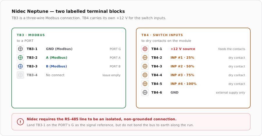
The Neptune is one of the better-documented motors on the pad: clearly labelled Modbus and switch-input terminal blocks, and a +12 V source to drive the inputs. The catch is that Nidec does not publish the protocol — you have to ask them for it.
Two ways in
Modbus (TB3)
Switch inputs (TB4)
Conductors
Three — A, B and ground
One per input, plus a source and ground
Signal
RS-485 differential
Switch closure carrying +12 V
Module output
PORT A or PORT B
Up to four dry contacts
Control
Full speed control
Four fixed steps at 25% increments
Priority
Overrides the motor's own UI
INP #4 highest, UI lowest
Modbus on TB3
Terminal
Function
iSmart Module
TB3-1
GND (Modbus)
PORT terminal G
TB3-2
A (Modbus)
PORT terminal A
TB3-3
B (Modbus)
PORT terminal B
TB3-4
No connect
Leave empty
Nidec labels these terminals explicitly, which removes the usual guesswork. TB3-4 is deliberately unused.
Two blocks, two methods. TB3 is a three-wire Modbus connection; TB4 needs the +12 V on pin 1 switched into an input.
Discrete switch inputs on TB4
The fallback is four switch inputs that run the motor at fixed steps. Unlike the Century motors, these do not need a supply of your own: TB4-1 provides +12 V, and a dry contact switches it into whichever input you want. An external DC supply can be used instead, in which case its ground must be tied to the TB4-6 ground terminal.
Terminal
Function
TB4-1
+12 V source
TB4-2
INP #1
TB4-3
INP #2
TB4-4
INP #3
TB4-5
INP #4
TB4-6
GND
Input
Step
RPM at default limits
Priority
INP #4
100%
3450
Highest
INP #3
75%
2730
INP #2
50%
2011
INP #1
25%
1291
Lowest
Speeds are 25% increments of the standard range. The RPM figures assume the default 600 minimum and 3450 maximum — change either and every figure moves.
Priority runs from INP #4 downward, with the motor's own user interface lowest. Drive one input at a time and treat the hierarchy as a safety net rather than a control strategy.
The auxiliary load relay
The Neptune has an optional auxiliary load relay that closes automatically at 2100 RPM, intended to enable equipment that depends on flow — a chlorine generator, a heater or a cleaner. It is worth knowing about even if you do not use it, because it may already be doing some of the interlocking on an existing installation.
The DIP switch is voltage selection only
When it does not respond
Symptom
Where to look first
No Modbus communication
Swap A and B, then confirm Remote Control is enabled at the motor's UI.
Motor ignores the bus and runs a fixed speed
A switch input is asserted. INP #4 down to INP #1 all outrank the bus.
Nothing happens when a contact closes
The input needs +12 V through it. Confirm TB4-1 is landed, or that an external supply has its ground tied to TB4-6.
Comm-lost faults after a period of running
Check the connections at the drive interface board and the run back to the controller; the manual treats these as wiring faults first.
Speeds do not match the table
The motor's minimum or maximum RPM has been changed from the defaults.
iSmart Module relay driver board — KiCad schematic and BOM. PORT A-D are an unbuffered RS-485 pass-through carrying A, B and G; H1/H2 and AUX1/AUX2 are the only dry relay contacts, and the board provides no switch inputs