
Moov VSP Pumps
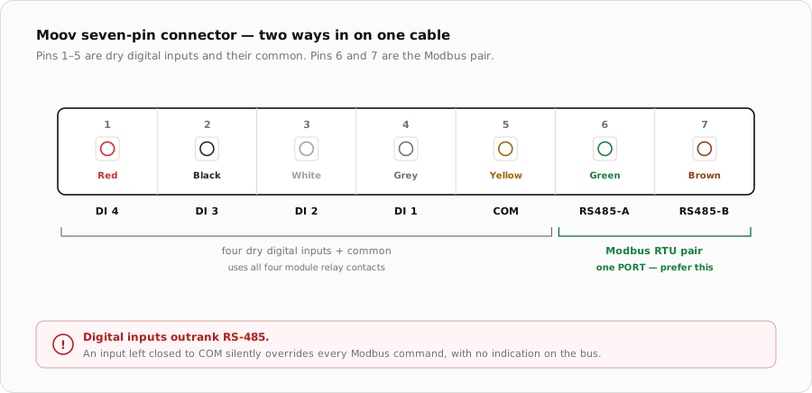
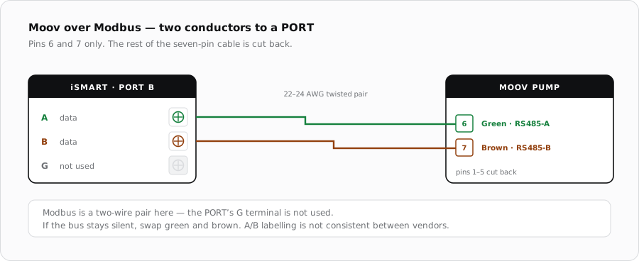
Moov brings everything out on a single seven-pin connector supplied with the pump: four digital inputs, a common, and a Modbus RS-485 pair. Use the pair.
The seven-pin connector
Moov supplies the communication cable with the pump. Use it rather than making one up — the pump end is moulded, and the conductor colours are what identify the functions at the far end. Cut back and terminate anything you do not use.
| Pin | Colour | Function | iSmart Module |
|---|---|---|---|
| 1 | Red | Digital Input 4 | Dry contact, if used |
| 2 | Black | Digital Input 3 | Dry contact, if used |
| 3 | White | Digital Input 2 | Dry contact, if used |
| 4 | Grey | Digital Input 1 | Dry contact, if used |
| 5 | Yellow | Digital ground (COM) | Common side of those contacts |
| 6 | Green | RS485-A | PORT terminal A |
| 7 | Brown | RS485-B | PORT terminal B |
Digital inputs, if you use them
| Input | Colour | Effect while closed to COM |
|---|---|---|
| Digital Input 1 | Grey | Pump forced to stop |
| Digital Input 2 | White | Run at 100% |
| Digital Input 3 | Black | Run at 80% |
| Digital Input 4 | Red | Run at 40% |
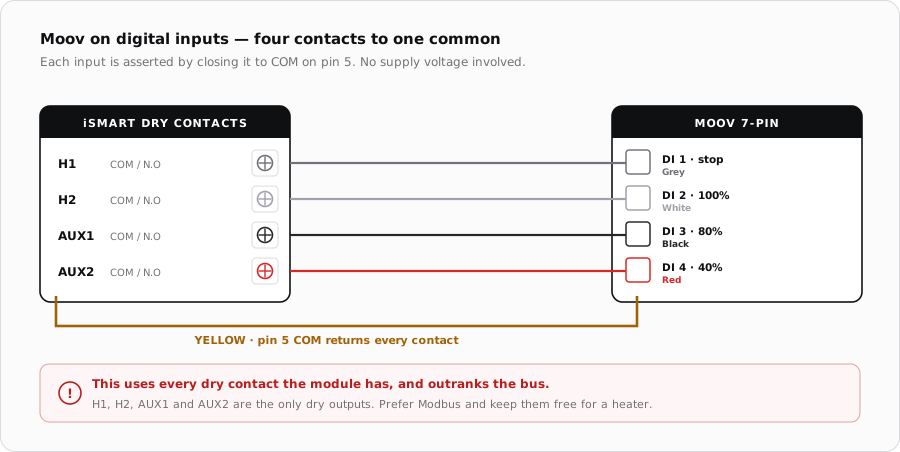
Releasing an input returns control to the panel rather than to the bus, so digital inputs are best treated as an override, not a control strategy.
Cable
- Use the supplied cable where the run allows it.
- If extending, keep green and brown as one twisted pair in shielded cable.
- Ground the shield at the iSmart Module end only.
- Keep it out of conduit shared with the pump's power wiring.
When it does not respond
| Symptom | Where to look first |
|---|---|
| Modbus commands ignored | A digital input is closed to common somewhere. |
| No communication at all | Swap green and brown, then check address and serial settings. |
| Runs at a fixed speed | An input is asserted — the pump is obeying it, not you. |
| Returns to panel control unexpectedly | An input was released; control falls back to the panel, not the bus. |
Sources
- Moov VS Pump Inverter Pool Pump manual (MP10VSP / MP15VSP / MP165VSP) — the seven-pin connector colours and digital input behaviour
- iSmart Module relay driver board — KiCad schematic and BOM. PORT A-D are an unbuffered RS-485 pass-through; H1/H2 and AUX1/AUX2 are the only dry relay contacts