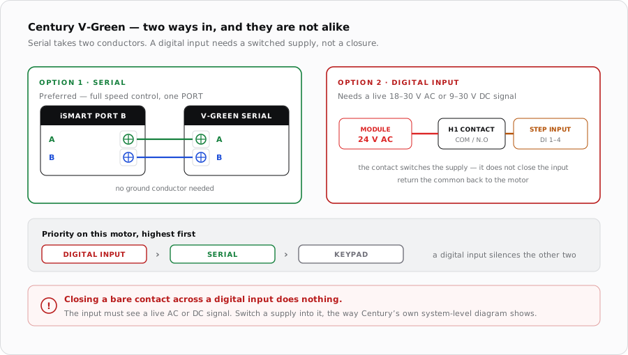
V-Green motors offer a serial connection on two wires or four digital inputs. Take the serial route if you can: the digital inputs need a switched supply rather than a dry contact, and once one is present the motor stops listening to the bus entirely.
Two ways in
Serial
Digital inputs
Conductors
Two — A and B
One per input, plus a common return
Signal
RS-485 differential
Live 18-30 V AC or 9-30 V DC
Module output
PORT A or PORT B
A dry contact switching a supply
Control
Full speed control
Four fixed programmed speeds
Priority
Overridden by digital inputs
Highest priority of all
Serial is the better result — one pair of conductors, full speed control, and it leaves the module's dry contacts free for other equipment. The digital inputs exist for controllers that cannot do better.
Serial connection
The motor has a dedicated serial connector on the top of the drive, separate from the digital input connector and the DIP switches. Only two conductors are needed: A and B. There is no ground conductor on this connection.
Century
iSmart Module
A
PORT terminal A
B
PORT terminal B
Serial on the left needs two conductors. A digital input needs a switched supply, not a closure.
Digital inputs
The practical arrangement is the one Century shows in its own system-level control diagram: a relay per input, switching a supply into it. On the iSmart Module that means using a dry contact — H1, H2, AUX1 or AUX2 — to switch 24 V AC from the module's own 24 V AC supply into the chosen input. Wire COM and N.O so each rests open and the motor sees nothing when the module is unpowered.
Input
Runs
Priority
Digital Input 4
OVERRIDE speed
Highest
Digital Input 3
STEP 3 speed
Digital Input 2
STEP 2 speed
Digital Input 1
STEP 1 speed
Lowest
The four inputs map to the motor's programmed speeds. Their timing is direct — there is no schedule behind a digital input.
If more than one input is asserted the motor takes the highest-numbered one, so OVERRIDE beats STEP 3, which beats STEP 2, which beats STEP 1. Treat that as a safety net rather than a control strategy and drive one input at a time. Removing every input returns the motor to its 24 hour schedule, provided START was pressed before the input was applied.
Behaviour worth knowing before you commission
When it does not respond
Symptom
Where to look first
Serial commands ignored
A digital input is present. Check the panel LEDs — a blinking STEP LED with the START LED off means an input is in control.
Nothing happens when a contact closes
The inputs need a live supply, not a closure. Confirm 18-30 V AC or 9-30 V DC is actually reaching the input.
No serial communication at all
Swap A and B, then confirm the adapter kit is fitted if the motor needs one.
Motor restarts a minute after stopping
An over-current fault clearing itself, not a control fault.
Motor restarts four minutes after STOP
Expected under serial or digital control. Isolate at the breaker instead.
Wrong speed on an input
Another input is also asserted and the higher number is winning.
iSmart Module relay driver board — KiCad schematic and BOM. PORT A-D are an unbuffered RS-485 pass-through; H1/H2 and AUX1/AUX2 are the only dry relay contacts; a 24 V AC supply is present on the board for the valve outputs